|
Making Small Robotic Wheels Making Servo Mounted Wheels:
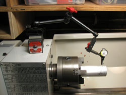
Step 1: Use a bandsaw or cut-off saw to cut off a piece approximately 3 1/2" (85 mm) long from the 1 1/2" aluminum stock. Source of 1 1/2" aluminum stock: MSC Industrial Supply Co. Part #02629426. Step 2: With a "Last Word" Dial Test Indicator, center the stock in the lathe chuck to remove as much wobble as is reasonably possible. Our small bench lathe will not permit the 1 1/2" stock to go through the spindle.
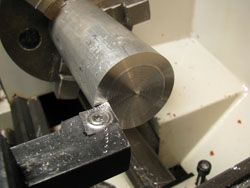
Step 3: Face and turn stock. You may want to perform Step 5 before turning the stock inorder to provide support for the free end.
Step 4: Face outer wheel design.
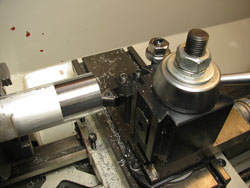
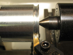
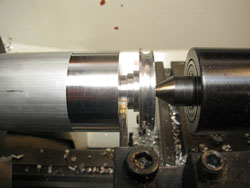
Step 5: Center drill the stock and support free end with a live center inserted into the tailstock.
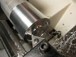
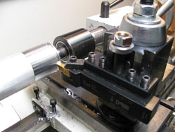
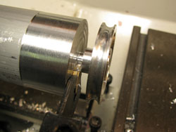
Step 6: Turn groove for O-ring. Tool holder for insert: Dorian NSR 12-3B. Positive Radius Grooving Insert: Agi-VR/Wesson VRR-3094R VR772, search VRR-3094R on Agi-VR/Wesson site. (Radius = 0.094" (48 mm)). Source: Anich Industries.
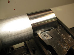
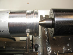
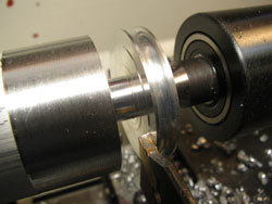
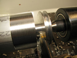
Step 7: Set-up toolpost with parting tool to cut shaft notch. Cut notch in 3 steps. Leave a little extra width of the flat outer surface to the left of the groove when cutting the notch.
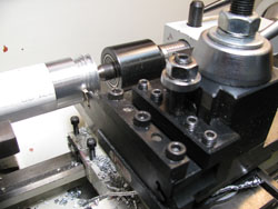
Step 8: Face the inside surface of the wheel and at the same time make the flat outer surface to the left of the groove the same width as on the right side of the groove.
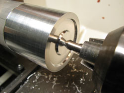
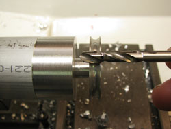
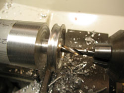
Step 9: Select a drill bit slightly larger than the motor shaft and mark the bit such that the drill bit will not penetrate where the parting will take place. Make sure that you have enough shaft left after parting to accommodate the set screw. Drill the hole into the face.
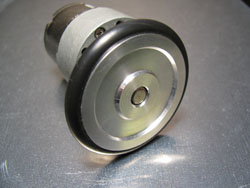
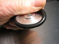
Step 10: Part wheel from stock and insert the O-ring. O-Rings: 3/16" Cross Section x 1 1/4 ID x 1 5/8 OD O-Ring. Source MSC Part #75749572.
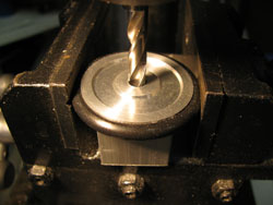
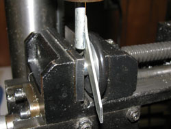
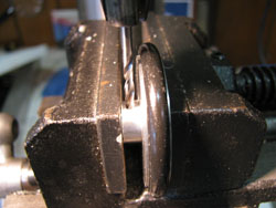
Step 11: Finish drilling motor shaft hole on a drill press. use a hollow square extrusion to support the wheel.
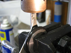
Step 12: Locate the center of the set screw shaft.
Step 13: Drill set screw hole in shaft and tap for set screw.
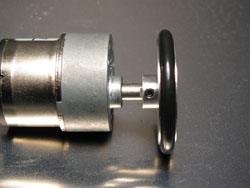
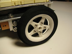
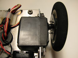
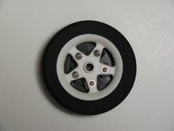
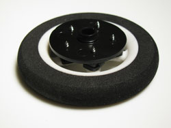
Making Servo Mounted Wheels: This section mounts the Maxx Products 2.5” light foam wheels (EPW250) onto a round servo horn. Alternate wheels are the Du-Bro 2.5” Micro Sport Wheels – Cat No. 250MS. A finished wheel is shown below:
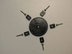
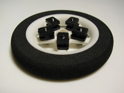
The photos below show the Futaba servo parts used and some assembly details.
|
|||||||||||||||||||||||||||||||||||||||||||||||||||||||||||||||||||||